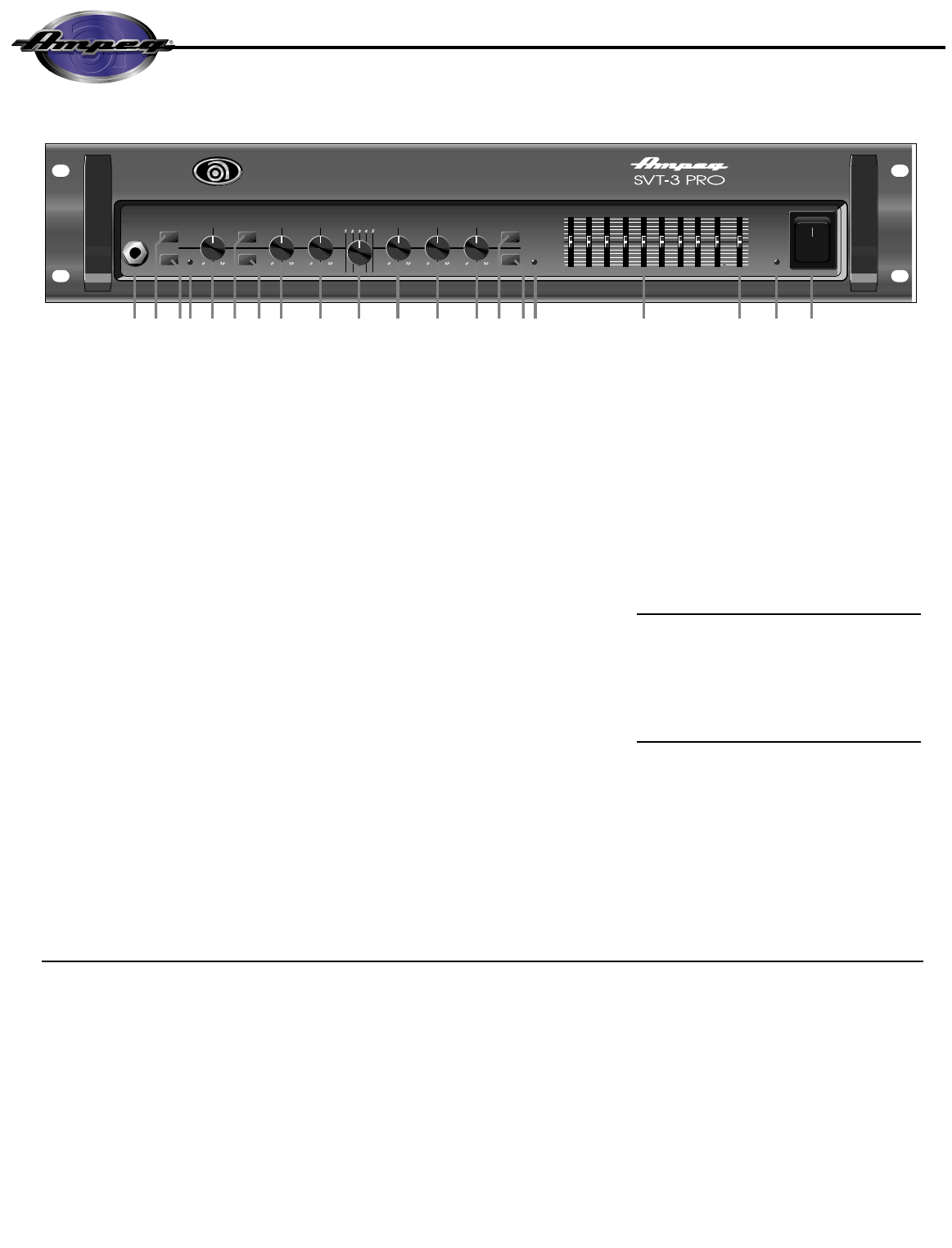
1. INPUT: The signal output from an instrument
(active or passive) or a line level signal may be con-
nected here by means of a shielded instrument
cable.
2. BRIGHT: This switch, when depressed, adds a
more lively top end response to the input signal.
3. -15dB: This switch, when depressed, attenuates
the input signal by 15dB. Attenuation allows the Gain
control (#5) to be used over a larger portion of its
range. If clipping is indicated with the Gain control
way down, attenuation is needed.
4. PEAK LED: This LED flashes when the signal
level into the preamp (excluding the graphic EQ)
approaches clipping. Adjust the Gain control (#5) until
a strong signal from your instrument causes this LED
to flicker.
NOTE: If the LED flashes frequently with the Gain at
a low setting, use the -15dB switch (#3) to attenuate
the input signal and readjust the Gain.
5. GAIN:This serves as the input level control for the
amplifier. For the best signal to noise ratio set this
control so the Peak LED (#3) flashes when you strike
a string fairly hard.
6. ULTRA HIGH: This switch, when depressed,
enhances the amount of high frequency output by
6dB at 5kHz.
7. ULTRA LOW: This switch, when depressed,
greatly enhances the amount of low-end bass tones
which you can feel and hear, especially the low E and
low B strings (of a 5-string bass).
8. BASS: This is the primary low frequency control
which allows for 12dB of cut or boost at 50Hz.
9. MIDRANGE: This is the primary midrange control
which allows for 15dB of cut or boost at the center
frequency selected by the Frequency control (see
#10).
10. FREQUENCY: This control allows you to select
the center frequency for the midrange control, giving
you a choice of five “voices” for the midrange. The
numbers correspond to the following center frequen-
cies: 1=220Hz, 2=450Hz, 3=800Hz, 4=1.6kHz,
5=3kHz.
11. TREBLE: This is the primary high frequency
control which allows for 19dB of cut or 14dB of boost
at 5kHz.
12. MASTER: Set the overall output level of the
amplifier with this control.
13. TUBE GAIN: The tube gain control varies the
high voltage supply to the power amp tubes. This
allows a variety of tonal response characteristics from
the power amp and replaces the limiter found on typ-
ical solid state power amps. At “10” the voltage is at
maximum, providing a dynamic, highly responsive
tone. At “0” the voltage is at minimum, offering a thick-
ened, more compressed tone. This tone can also be
distorted, depending on volume level. In between set-
tings are best for preventing harsh distortion when
driving the power amp to its limits. The effect of this
control increases from moderate to dramatic as the
power amp is driven harder.
NOTE: When adjusting the tube gain control from
“10” to “0” rapidly, a low frequency hum as well as
muting of the output signal occur simultaneously. This
is due to shifting of the DC bias point of the tubes, and
is no cause for concern. Adjusting the control quickly
from “0” to “10” brings a moderate delay due to the
power supply capacitors charging.
14. MUTE: Use this switch to mute all outputs except
the Tuner Out (rear panel #28). The footswitch can
also control muting, if the Mute switch on the front
panel is left in the “out” position. (The front panel
switch is still active with the footswitch connected.
This is excellent for tuning your bass with an electric
tuner without having to adjust any levels to turn down
your sound.)
15. GRAPHIC EQ: This switch, when depressed,
enables the 9-band Graphic EQ (see #17 & #18). A
footswitch overrides this switch.
16. ACTIVE LED: This LED illuminates when the EQ
is on.
17. 9-BAND GRAPHIC EQ: These sliders control
the output frequencies indicated above each control.
The center position of each control is flat (no boost or
cut).
The Graphic EQ can be used in two ways: 1) To fine tune
your sound, make small adjustments at the desired fre-
quencies and leave the EQ on throughout the entire ses-
sion. (This is great for adapting to varying room acoustics
when going from club to club, etc.) 2) For a completely dif-
ferent sound, make larger adjustments and only activate the
EQ when you want a “second channel” sound (such as dur-
ing bass solos).
18. LEVEL:This slider is the output volume control for
the Graphic EQ and only affects the signal when the
EQ is engaged. If the EQ’d signal is too soft, slide the
Level control up; if it’s too loud, slide this control down.
19. ON LED: This LED illuminates when the Power
is ON.
20. POWER: This heavy-duty rocker switch applies
the power to the amplifier: the amp is ON when the
top of the switch is depressed, OFF when the bottom
of the switch is depressed.
NOTE: There is a delay during power up until the pro-
tection relay enables the power amplifier output.
1. ENTRADA: Conecte aquí su guitarra de bajos
utilizando un cable blindado para instrumentos.
2. BRILLANTE: Este interruptor, cuando se encuen-
tre ADENTRO, añade a la señal de entrada una
respuesta más viva en la parte alta. Usted puede
experi-mentar el uso de diferentes posi-ciones del
EQ con este interruptor.
3. -15dB: Este interruptor, cuando se encuentre
ADENTRO, atenuará en 15dB la señal de entrada.
Si su bajo tiene circuitos electrónicos activos, usted
tal vez quiera usar este interruptor.
4. DIODO LED DE PICOS: Este LED se iluminará
cuando el nivel de preamplificación esté cerca del
nivel de aplanamiento "clipping", lo que indicaría una
posición de ganancia óptima.
5. GANANCIA: Esto controla la ganancia del pre-
amplificador.
6. ULTRA AGUDOS: Cuando se oprime hacia
ADENTRO, este interruptor realza la cantidad de la
salida de frecuencias altas en 6dB a 5kHz.
7. ULTRA GRAVES: Al oprimirse este interruptor
hacia ADENTRO, se realza en gran forma la canti-
dad de tonos bajos de la parte grave que usted
puede sentir y oír, en especial de las cuerdas de E
bajo y B bajo (en un bajo de 5 cuerdas).
8. BAJOS: Es el control primordial para las frecuen-
cias bajas. Permite 12dB de recorte (totalmente a la
izquierda) ó refuerzo (totalmente a la derecha) a
50Hz. La salida de frecuencias graves queda plana
en la posición central.
9. RANGO MEDIANO: Es el control primordial en el
rango mediano. Permite 15dB de recorte (totalmente
a la izquierda) ó refuerzo (totalmente a la derecha) a
la frecuencia central que se haya seleccionado en el
control de Frecuencias (véase #10). La salida del
rango mediano está plana en la posición central.
10.FRECUENCIA: Le permite seleccionar la fre-
cuencia central para el control del rango mediano, lo
que le da la opción de cinco "voces" para el rango
mediano. Las frecuencias correspondientes son:
1=220Hz, 2=450Hz, 3=800Hz, 4=1.6kHz, 5=3kHz.
11. AGUDOS: Es el control primordial para las fre-
cuencias altas. Permite 19dB de recorte (totalmente
a la izquierda) ó 14dB de refuerzo (totalmente a la
derecha) a 5kHz. La salida de frecuencias altas es
 (8 pages)
 (12 pages)
 Manymanuals.com
 Manymanuals.de
 Manymanuals.fr
 Manymanuals.it
 Manymanuals.pl
 Manymanuals.cz
 Manymanuals.es
 Manymanuals-pt.com
Comments to this Manuals